相关阅读:MCU微课堂 | CKS32K148 SCG(一)
六、SCG寄存器配置
在前文中,已经对SCG时钟进行了整体介绍,下面以RUN模式下配置SPLL为系统时钟源为例,对时钟配置的具体方法进行讲解。
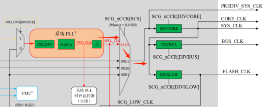
图5 SYSCLK生成流程
在RUN模式下选择SPLL作为系统时钟源时,应对SPLL时钟进行相关使能操作,同时应保证SPLL的输出信号频率在正常工作频率90~160MHz范围内。在对SPLL的配置中,有两个较为重要的寄存器,分别是SCG_SPLLCSR和SCG_SPLLCFG。
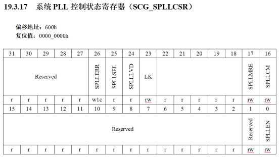
图6 SCG_SPLLCSR寄存器
在SCG_SPLLCSR寄存器中,我们应重点关注如下几位:

图7 SPLL系统时钟选择与有效位

图8 SPLL时钟使能位
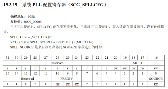
图9 SCG_SPLLCFG寄存器
在SCG_SPLLCFG寄存器中,我们应关注如下两位:
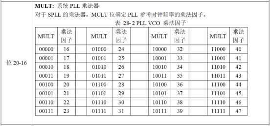
图10 SPLL倍频系数位
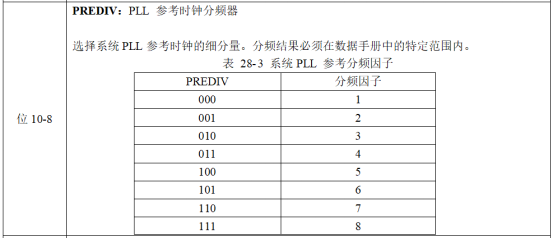
图11 SPLL分频系数位
可知,SPLL对参考时钟信号能够进行16~47倍频和最大8分频。
由于SPLL以SOSC作为参考时钟源,还应在寄存器SCG_SOSCCSR中对SOSC时钟使能。
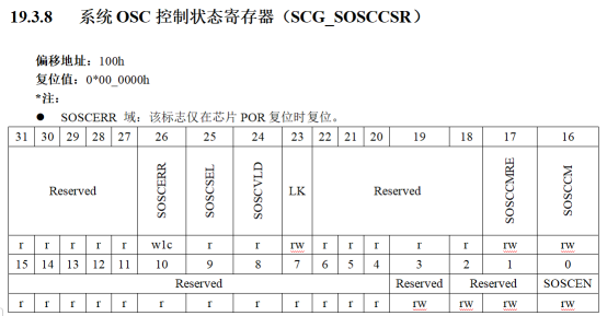
图12 SCG_SOSCCSR寄存器
SCG_SOSCCSR寄存器中,SOSC时钟使能的相关位如下:

图13 SOSC时钟有效位

图14 SOSC时钟使能位
在完成上述时钟配置后,在寄存器SCG_RCCR中配置RUN模式下的系统时钟源。
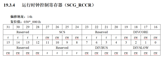
图15 SCG_RCCR寄存器
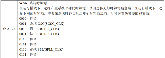
图16 系统时钟源选择位
除SPLL时钟外,还应保证生成的内部时钟SYS_CLK、BUS_CLK和FLASH_CLK工作在安全频率范围内。下图为系统时钟源信号(紫色)生成内部时钟信号的流程图。
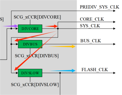
图17 内部时钟生成流程
生成的内部时钟信号频率由寄存器SCG_RCCR中如下相关位调控:

图18 内核时钟分频位

图19 总线时钟分频位

图20 FLASH时钟分频位
七、SCG结构体初始化
在标准库中,所有时钟的初始化均可通过CLOCK_DRV_Init()实现:
CLOCK_DRV_Init(&clockMan1_InitConfig0);
其中使用的参数结构体指针clockMan1_InitConfig0,其结构体类型为clock_manager_user_config_t,结构体定义如下:
typedef struct
{
    scg_config_t                scgConfig;      /*!< SCG Clock configuration.  */
    sim_clock_config_t           simConfig;     /*!< SIM Clock configuration. */
    pcc_config_t                 pccConfig;     /*!< PCC Clock configuration. */
    pmc_config_t               pmcConfig;      /*!< PMC Clock configuration.  */
} clock_manager_user_config_t;
需要注意的是,由于SCG相关时钟的配置仅需在第一个成员结构体scgConfig中进行,对于其余的成员结构体的使用本文中将不进行介绍。
SCG的初始化结构体类型为scg_config_t,下面是相关结构体的定义:
typedef struct
{
    scg_sirc_config_t         sircConfig;      /*!< Slow internal reference clock configuration.*/
    scg_firc_config_t         fircConfig;      /*!< Fast internal reference clock configuration. */
    scg_sosc_config_t         soscConfig;      /*!< System oscillator configuration.        */
    scg_spll_config_t         spllConfig;      /*!< System Phase locked loop configuration.  */
    scg_rtc_config_t          rtcConfig;       /*!< Real Time Clock configuration.         */
    scg_clockout_config_t     clockOutConfig;  /*!< SCG ClockOut Configuration.           */
    scg_clock_mode_config_t   clockModeConfig; /*!< SCG Clock Mode Configuration.        */
} scg_config_t;
在本文中,我们需要使用上述结构体中的成员结构体soscConfig、spllConfig以及clockModeConfig完成对内部时钟输出的配置。
对于SOSC时钟,初始化结构体类型为scg_sosc_config_t,结构体定义如下:
typedef struct
{
    uint32_t  freq;                         /*!< System OSC frequency.  */
    scg_sosc_monitor_mode_t monitorMode;   /*!< System OSC Clock monitor mode.  */
    scg_sosc_ext_ref_t extRef;                /*!< System OSC External Reference Select.*/
    scg_sosc_gain_t    gain;                /*!< System OSC high-gain operation. */
    scg_sosc_range_t   range;              /*!< System OSC frequency range.  */
    scg_async_clock_div_t div1;              /*!< Asynchronous peripheral source.  */
    scg_async_clock_div_t div2;              /*!< Asynchronous peripheral source.  */
    bool enableInStop;                     /*!< System OSC is enable or not in stop mode. */
    bool enableInLowPower;                /*!< System OSC is enable or not in low power mode.*/
    bool locked;                          /*!< System OSC Control Register can be written. */
    bool initialize;                         /*!< Initialize or not the System OSC module.*/
} scg_sosc_config_t;
该结构体中共有11个成员变量,我们仅需配置其中的第1、4、5和11号变量即可完成对SOSC时钟的使能,其功能分别如下:
变量一freq:应配置为当前SOSC使用的时钟源频率。
变量四gain:用于控制晶振操作的功耗模式,可选高增益或低增益。
变量五range:用于为OSC选择频率范围,作为SPLL的时钟源,本文中SOSC只能选择高频率范围。
变量十一initialize:用于对SOSC时钟进行使能,决定了时钟是否有效。
对于SPLL时钟,初始化结构体类型为scg_spll_config_t,结构体定义如下:
typedef struct
{
    scg_spll_monitor_mode_t monitorMode; /*!< Clock monitor mode selected.  */
    uint8_t        prediv;               /*!< PLL reference clock divider.  */
    uint8_t        mult;                /*!< System PLL multiplier.  */
    uint8_t        src;                 /*!< System PLL source.  */
    scg_async_clock_div_t div1;           /*!< Asynchronous peripheral source.*/
    scg_async_clock_div_t div2;           /*!< Asynchronous peripheral source.*/
    bool enableInStop;                  /*!< System PLL clock is enable or not in stop mode. */
    bool locked;                        /*!< System PLL Control Register can be written. */
    bool initialize;                      /*!< Initialize or not the System PLL module. */
} scg_spll_config_t;
该结构体中共有9个成员变量,我们需配置其中的第2、3、4和9号变量以完成对SPLL时钟的使能以及输出频率调控,其功能分别如下:
变量二prediv:用于配置SPLL参考时钟频率的分频系数。
变量三mult:用于配置SPLL参考时钟频率的乘法因子。
变量四src:用于配置SPLL的输入时钟源,在本文中仅能选择参考时钟SOSC作为时钟源。
变量九initialize:用于对SPLL时钟进行使能,决定了时钟是否有效。
对于RUN模式下的内部时钟配置,初始化结构体类型为scg_system_clock_config_t,结构体定义如下:
typedef struct
{
    scg_system_clock_div_t divSlow;     /*!< Slow clock divider. */
    scg_system_clock_div_t divBus;      /*!< BUS clock divider.*/
    scg_system_clock_div_t divCore;     /*!< Core clock divider. */
    scg_system_clock_src_t src;         /*!< System clock source. */
} scg_system_clock_config_t;
该结构体中共有4个成员变量,其功能分别如下:
变量一divSlow:用于控制FLASH时钟分频比。
变量二divBus:用于控制总线时钟分频比。
变量三divCore:用于控制内核时钟分频比。
变量四src:用于在运行模式下,选择产生系统时钟的时钟源。
八、时钟配置代码
依据前文中对寄存器与SCG时钟结构体的基本介绍,即可在函数CLOCK_DRV_Init()中对系统时钟进行相关配置。本文以SPLL为时钟源,配置输出56MHz的SYSCLK、28MHz的BUSCLK以及14MHz的FLASHCLK。相关结构体代码如下:
clock_manager_user_config_t clockMan1_InitConfig0 =
{
    .scgConfig =
    {
        .soscConfig =
        {
            .initialize = true,
            .freq = 8000000U,                      /* System Oscillator frequency: 8MHz */
            .extRef = SCG_SOSC_REF_OSC,            /* Internal oscillator of OSC requested. */
            .range = SCG_SOSC_RANGE_HIGH,       /* High frequency range selected for the crystal oscillator of 8 MHz to 40 MHz. */
        },
        .spllConfig =
        {
            .initialize = true,
            .prediv = (uint8_t)SCG_SPLL_CLOCK_PREDIV_BY_1,/* Divided by 1 */
            .mult = (uint8_t)SCG_SPLL_CLOCK_MULTIPLY_BY_28,/* Multiply Factor is 28 */
            .src = 0U,                             /*Clock Source SOSC*/
        },
        .clockModeConfig =
        {
            .initialize = true,.rccrConfig =
            {
                .src = SCG_SYSTEM_CLOCK_SRC_SYS_PLL,   /* System PLL */
                .divCore = SCG_SYSTEM_CLOCK_DIV_BY_2,  /* Core Clock Divider: divided by 2 */
                .divBus = SCG_SYSTEM_CLOCK_DIV_BY_2,   /* Bus Clock Divider: divided by 2 */
                .divSlow = SCG_SYSTEM_CLOCK_DIV_BY_4,  /* Slow Clock Divider: divided by 4 */
            },
        }
    }
};来源:中科芯MCU
免责声明:本文为转载文章,转载此文目的在于传递更多信息,版权归原作者所有。本文所用视频、图片、文字如涉及作品版权问题,请联系小编进行处理(联系邮箱:cathy@eetrend.com)。