
串口发送过程配置流程
HAL库中串口寄存器定义文件:
stm32f429xx.h F429芯片
stm32f767xx.h F767芯片
stm32f103xx.h F103芯片
stm32fnnnx.x.h 其他芯片
可以在其中找到USART_TypeDef:最终会映射到寄存器的地址。
typedef struct
{
  __IO uint32_t CR1;    /*!< USART Control register 1,                 Address offset: 0x00 */
  __IO uint32_t CR2;    /*!< USART Control register 2,                 Address offset: 0x04 */
  __IO uint32_t CR3;    /*!< USART Control register 3,                 Address offset: 0x08 */
  __IO uint32_t BRR;    /*!< USART Baud rate register,                 Address offset: 0x0C */
  __IO uint32_t GTPR;   /*!< USART Guard time and prescaler register,  Address offset: 0x10 */
  __IO uint32_t RTOR;   /*!< USART Receiver Time Out register,         Address offset: 0x14 */
  __IO uint32_t RQR;    /*!< USART Request register,                   Address offset: 0x18 */
  __IO uint32_t ISR;    /*!< USART Interrupt and status register,      Address offset: 0x1C */
  __IO uint32_t ICR;    /*!< USART Interrupt flag Clear register,      Address offset: 0x20 */
  __IO uint32_t RDR;    /*!< USART Receive Data register,              Address offset: 0x24 */
  __IO uint32_t TDR;    /*!< USART Transmit Data register,             Address offset: 0x28 */
} USART_TypeDef;
HAL库中串口函数定义文件:
stm32f7xx_hal_uart.c ,stm32f7xx_hal_usart.c
串口字节发送流程:
1、编程USARTx_CR1的M位来定义字长。
2、编程USARTx_CR2的STOP位来定义停止位位数。
3、编程USARTx_BRR寄存器确定波特率。
4、使能USARTx_CR1的UE位使能USARTx。
5、如果进行多缓冲通信,配置USARTx_CR3的DMA使能(DMAT)。具体请参考后面DMA实验。
6、使能USARTx_CR1的TE位使能发送器。
7、向发送数据寄存器TDR写入要发送的数据(对于M3,发送和接收共用DR寄存器)。
8、向TRD寄存器写入最后一个数据后,等待状态寄存器USARTx_SR(ISR)的TC位置1,传输完成。
对于stm32f4:控制寄存器 1 (USART_CR1):
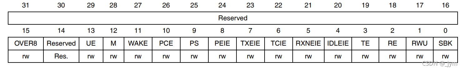
位12 M:字长 (Word length) 该位决定了字长。该位由软件置 1 或清零。
0:1 起始位,8 数据位,n 停止位
1:1 起始位,9 数据位,n 停止位
注意:在数据传输(发送和接收)期间不得更改 M 位
stm32f4控制寄存器 2 (USART_CR2):
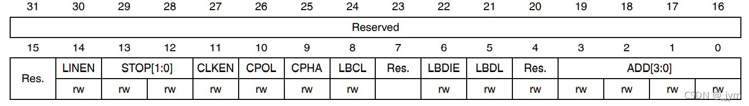
位 13:12 STOP:停止位 (STOP bit)
这些位用于编程停止位。
00:1 个停止位
01:0.5 个停止位
10:2 个停止位
11:1.5 个停止位
注意:0.5 个停止位和 1.5 个停止位不适用于 UART4 和 UART5。
串口字节发送流程中的1、2、3设置串口的一些参数。接下来要使能使用到的串口:
同样在stm32f4控制寄存器 1 (USART_CR1)中可以找到:
位 13 UE:USART 使能 (USART enable)
该位清零后,USART 预分频器和输出将停止,并会结束当前字节传输以降低功耗。此位由软件置 1 和清零。
0:禁止 USART 预分频器和输出
1:使能 USART
位 3 TE:发送器使能 (Transmitter enable)
该位使能发送器。该位由软件置 1 和清零。
0:禁止发送器
1:使能发送器
注意:
1:除了在智能卡模式下以外,传送期间 TE 位上的“0”脉冲(“0”后紧跟的是“1”)会在当前字的后面发送一个报头(空闲线路)。
2:当 TE 置 1 时,在发送开始前存在 1 位的时间延迟。
串口字节发送流程中的4、5、6步骤使能完成之后,接下来进行数据发送也就是7、8步骤。
串口字节发送流程(HAL库函数)
配置步骤①~⑥:配置字长,停止位,奇偶校验位,波特率等:
可以在stm32f7xx_hal_uart.c中找到:HAL_StatusTypeDef HAL_UART_Init(UART_HandleTypeDef *huart)函数:该函数内部会引用标识符__HAL_USART_ENABLE使能相应串口。
/**
  * @brief Initializes the UART mode according to the specified
  *         parameters in the UART_InitTypeDef and creates the associated handle .
  * @param huart: uart handle
  * @retval HAL status
  */
HAL_StatusTypeDef HAL_UART_Init(UART_HandleTypeDef *huart)
{
  /* Check the UART handle allocation */
  if(huart == NULL)
  {
    return HAL_ERROR;
  }

  if(huart->Init.HwFlowCtl != UART_HWCONTROL_NONE)
  {
    /* Check the parameters */
    assert_param(IS_UART_HWFLOW_INSTANCE(huart->Instance));
  }
  else
  {
    /* Check the parameters */
    assert_param(IS_UART_INSTANCE(huart->Instance));
  }

  if(huart->gState == HAL_UART_STATE_RESET)
  {
    /* Allocate lock resource and initialize it */
    huart->Lock = HAL_UNLOCKED;

    /* Init the low level hardware : GPIO, CLOCK */
    HAL_UART_MspInit(huart);
  }

  huart->gState = HAL_UART_STATE_BUSY;

  /* Disable the Peripheral */
  __HAL_UART_DISABLE(huart);

  /* Set the UART Communication parameters */
  if (UART_SetConfig(huart) == HAL_ERROR)
  {
    return HAL_ERROR;
  }

  if (huart->AdvancedInit.AdvFeatureInit != UART_ADVFEATURE_NO_INIT)
  {
    UART_AdvFeatureConfig(huart);
  }

  /* In asynchronous mode, the following bits must be kept cleared:
  - LINEN and CLKEN bits in the USART_CR2 register,
  - SCEN, HDSEL and IREN  bits in the USART_CR3 register.*/
  CLEAR_BIT(huart->Instance->CR2, (USART_CR2_LINEN | USART_CR2_CLKEN));
  CLEAR_BIT(huart->Instance->CR3, (USART_CR3_SCEN | USART_CR3_HDSEL | USART_CR3_IREN));

  /* Enable the Peripheral */
  __HAL_UART_ENABLE(huart);

  /* TEACK and/or REACK to check before moving huart->gState and huart->RxState to Ready */
  return (UART_CheckIdleState(huart));
}
步骤⑦~⑧发送数据和等待发送完成:可以在stm32f7xx_hal_uart.c中找到:HAL_UART_Transmit函数:
HAL_StatusTypeDef HAL_UART_Transmit(UART_HandleTypeDef *huart, uint8_t *pData, uint16_t Size, uint32_t Timeout)
__weak关键字:
函数前面加__weak修饰符,我们称之为弱函数。对于弱函数,用户可以在用户文件中重新定义一个同名函数,最终编译器编译的时候会选择用户定义的函数。如果用户没有定义,那么函数内容就是弱函数定义的内容。
函数声明:
可以在stm32f7xx_hal_uart.h中找到:void HAL_UART_MspInit(UART_HandleTypeDef *huart);
函数定义(弱函数):里面不做事
__weak void HAL_UART_MspInit(UART_HandleTypeDef *huart)
{
}
弱函数被其他函数调用:
HAL_StatusTypeDef HAL_UART_Init(UART_HandleTypeDef *huart)
{
if(huart->gState == HAL_UART_STATE_RESET)
{
/* Allocate lock resource and initialize it */
huart->Lock = HAL_UNLOCKED;
/* Init the low level hardware : GPIO, CLOCK */
HAL_UART_MspInit(huart);
}
}为什么要定义一个弱函数?
因为在hal库里面有其他的函数需要调用这样一个函数,但是里面的内容还不确定如何初始化,所以先定义一个weak函数。然后用户在可以再去编写函数的真正内容。这样的话不会报函数重定义的错误。运行流程一样,但是初始化可能不一样,使用weak函数的话,好处是我们不会对既有程序流程做任何修改,只需要修改流程中的某部分与用户相关的代码即可。
弱函数重新被定义:
void HAL_UART_MspInit(UART_HandleTypeDef *huart)
{
…//内容
}
__weak关键字的好处:
对于事先已经定义好的一个流程,我们只希望修改流程中的某部分与用户相关的代码,这个时候我们可以采用弱函数定义一个空函数,然后让用户自行定义该函数。这样做的好处是我们不会对既有程序流程做任何修改。
HAL库中大量使用__weak关键字修饰外设回调函数。
外设回调函数供用户编写MCU相关程序,大大提高程序的通用性移植性。
串口发送程序配置过程(HAL库):
1、初始化串口相关参数,使能串口:HAL_UART_Init();
2、串口相关IO口配置,复用配置:在HAL_UART_MspInit中调用HAL_GPIO_Init函数。
3、发送数据,并等待数据发送完成:HAL_UART_Transmit()函数;
然后根据上面的流程,开始编写代码:
初始化串口相关参数HAL_UART_Init();
先编一个初始化函数:
void uart1_init(void)
{

}
然后在HALLIB-stm32f7xx_hal_uart.c中找到:HAL_UART_Init函数,粘贴到初始化函数里,调用它:
然后发现他有一个入口参数UART_HandleTypeDef *huart是结构体指针部分。然后找到UART_HandleTypeDef的定义,可以找到:这个是串口句柄
typedef struct
{
  USART_TypeDef            *Instance;        /*!< UART registers base address        */

  UART_InitTypeDef         Init;             /*!< UART communication parameters      */

  UART_AdvFeatureInitTypeDef AdvancedInit;   /*!< UART Advanced Features initialization parameters */

  uint8_t                  *pTxBuffPtr;      /*!< Pointer to UART Tx transfer Buffer */

  uint16_t                 TxXferSize;       /*!< UART Tx Transfer size              */

  uint16_t                 TxXferCount;      /*!< UART Tx Transfer Counter           */

  uint8_t                  *pRxBuffPtr;      /*!< Pointer to UART Rx transfer Buffer */

  uint16_t                 RxXferSize;       /*!< UART Rx Transfer size              */

  uint16_t                 RxXferCount;      /*!< UART Rx Transfer Counter           */

  uint16_t                 Mask;             /*!< UART Rx RDR register mask          */

  DMA_HandleTypeDef        *hdmatx;          /*!< UART Tx DMA Handle parameters      */

  DMA_HandleTypeDef        *hdmarx;          /*!< UART Rx DMA Handle parameters      */

  HAL_LockTypeDef           Lock;            /*!< Locking object                     */

  __IO HAL_UART_StateTypeDef    gState;      /*!< UART state information related to global Handle management
                                                  and also related to Tx operations.
                                                  This parameter can be a value of @ref HAL_UART_StateTypeDef */

  __IO HAL_UART_StateTypeDef    RxState;     /*!< UART state information related to Rx operations.
                                                  This parameter can be a value of @ref HAL_UART_StateTypeDef */

  __IO uint32_t             ErrorCode;   /*!< UART Error code                    */

}UART_HandleTypeDef;
USART_TypeDef是串口的类型。在文件中可以找到:
#define USART2              ((USART_TypeDef *) USART2_BASE)
#define USART3              ((USART_TypeDef *) USART3_BASE)
#define UART4               ((USART_TypeDef *) UART4_BASE)
#define UART5               ((USART_TypeDef *) UART5_BASE)
然后找到UART_InitTypeDef的定义,可以看到,是配置串口外设的一些特性参数。
typedef struct
{
  uint32_t BaudRate;                  /*!< This member configures the UART communication baud rate.
                                           The baud rate register is computed using the following formula:
                                           - If oversampling is 16 or in LIN mode,
                                              Baud Rate Register = ((PCLKx) / ((huart->Init.BaudRate)))
                                           - If oversampling is 8,
                                              Baud Rate Register[15:4] = ((2 * PCLKx) / ((huart->Init.BaudRate)))[15:4]
                                              Baud Rate Register[3] =  0
                                              Baud Rate Register[2:0] =  (((2 * PCLKx) / ((huart->Init.BaudRate)))[3:0]) >> 1      */

  uint32_t WordLength;                /*!< Specifies the number of data bits transmitted or received in a frame.
                                           This parameter can be a value of @ref UARTEx_Word_Length */

  uint32_t StopBits;                  /*!< Specifies the number of stop bits transmitted.
                                           This parameter can be a value of @ref UART_Stop_Bits */

  uint32_t Parity;                    /*!< Specifies the parity mode.
                                           This parameter can be a value of @ref UART_Parity
                                           @note When parity is enabled, the computed parity is inserted
                                                 at the MSB position of the transmitted data (9th bit when
                                                 the word length is set to 9 data bits; 8th bit when the
                                                 word length is set to 8 data bits). */

  uint32_t Mode;                      /*!< Specifies whether the Receive or Transmit mode is enabled or disabled.
                                           This parameter can be a value of @ref UART_Mode */

  uint32_t HwFlowCtl;                 /*!< Specifies whether the hardware flow control mode is enabled
                                           or disabled.
                                           This parameter can be a value of @ref UART_Hardware_Flow_Control */

  uint32_t OverSampling;              /*!< Specifies whether the Over sampling 8 is enabled or disabled, to achieve higher speed (up to fPCLK/8).
                                           This parameter can be a value of @ref UART_Over_Sampling */

  uint32_t OneBitSampling;            /*!< Specifies whether a single sample or three samples' majority vote is selected.
                                           Selecting the single sample method increases the receiver tolerance to clock
                                           deviations. This parameter can be a value of @ref UART_OneBit_Sampling */
}UART_InitTypeDef;
此时可以在初始化函数中写:
UART_HandleTypeDef usart1_handler;

void uart1_init(void)
{
	usart1_handler.Instance = USART1;
	usart1_handler.Init.BaudRate = 115200;
	usart1_handler.Init.WordLength = UART_WORDLENGTH_8B;
	usart1_handler.Init.StopBits = UART_STOPBITS_1;
	usart1_handler.Init.HwFlowCtl = UART_HWCONTROL_NONE;
	usart1_handler.Init.Mode = UART_MODE_TX_RX;
	usart1_handler.Init.Parity = UART_PARITY_NONE;
	HAL_UART_Init(&usart1_handler);
}
《这里面参数都有哪些怎么找?》可以首先在HALLIB-stm32f7xx_hal_uart.c找到assert_param(IS_UART_INSTANCE(huart->Instance));然后双击IS_UART_INSTANCE找到它的定义,可以发现如下代码:然后就知道都可以填啥参数了,可以选择USART1作为参数。其他的参数设置也是类似的方式。
#define IS_UART_INSTANCE(__INSTANCE__) (((__INSTANCE__) == USART1) || \
                                    ((__INSTANCE__) == USART2) || \
                                    ((__INSTANCE__) == USART3) || \
                                    ((__INSTANCE__) == UART4)  || \
                                    ((__INSTANCE__) == UART5)  || \
                                    ((__INSTANCE__) == USART6) || \
                                    ((__INSTANCE__) == UART7)  || \
                                    ((__INSTANCE__) == UART8))
串口相关IO口配置HAL_UART_MspInit
在HALLIB-stm32f7xx_hal_uart.h中可以找到HAL_UART_MspInit的声明:void HAL_UART_MspInit(UART_HandleTypeDef *huart);
现在编写这个函数:最终这个函数会被HAL_UART_Init调用。由于STM32有好几个UART串口,所以先进行判断
void HAL_UART_MspInit(UART_HandleTypeDef *huart)
{
	if(huart->Instance==UART1)
	{

	}
}
端口复用配置过程:
1.GPIO端口时钟使能。
__HAL_RCC_GPIOA_CLK_ENABLE(); //使能GPIO时钟
2.复用外设时钟使能。
比如你要将端口PA9,PA10复用为串口,所以要使能串口时钟。
__HAL_RCC_USART1_CLK_ENABLE(); //使能串口1时钟
3.端口模式配置为复用功能。 HAL_GPIO_Init函数。
GPIO_Initure.Mode=GPIO_MODE_AF_PP; //复用推挽输出
4.配置GPIOx_AFRL或者GPIOx_AFRH寄存器,将IO连接到所需的AFx。HAL_GPIO_Init函数。
GPIO_Initure.Alternate=GPIO_AF7_USART1;//复用为USART1
对于端口,需要设置GPIO_InitTypeDef *GPIO_Init参数。如下
typedef struct
{
  uint32_t Pin;       /*!< Specifies the GPIO pins to be configured.
                           This parameter can be any value of @ref GPIO_pins_define */

  uint32_t Mode;      /*!< Specifies the operating mode for the selected pins.
                           This parameter can be a value of @ref GPIO_mode_define */

  uint32_t Pull;      /*!< Specifies the Pull-up or Pull-Down activation for the selected pins.
                           This parameter can be a value of @ref GPIO_pull_define */

  uint32_t Speed;     /*!< Specifies the speed for the selected pins.
                           This parameter can be a value of @ref GPIO_speed_define */

  uint32_t Alternate;  /*!< Peripheral to be connected to the selected pins.
                            This parameter can be a value of @ref GPIO_Alternate_function_selection */
}GPIO_InitTypeDef;
都设置完之后就是下面的串口相关IO口配置代码:
void HAL_UART_MspInit(UART_HandleTypeDef *huart)
{
	GPIO_InitTypeDef GPIO_Initure;
	if(huart->Instance==UART1)
	{
		__HAL_RCC_GPIOA_CLK_ENABLE();			//使能GPIOA时钟
		__HAL_RCC_USART1_CLK_ENABLE();			//使能USART1时钟
		GPIO_Initure.Pin=GPIO_PIN_9;			//PA9
		GPIO_Initure.Mode=GPIO_MODE_AF_PP;		//复用推挽输出
		GPIO_Initure.Pull=GPIO_PULLUP;			//上拉
		GPIO_Initure.Speed=GPIO_SPEED_HIGH;		//高速
		GPIO_Initure.Alternate=GPIO_AF7_USART1;	//复用为USART1
		HAL_GPIO_Init(GPIOA,&GPIO_Initure);	   	//初始化PA9

		GPIO_Initure.Pin=GPIO_PIN_10;			//PA10
		HAL_GPIO_Init(GPIOA,&GPIO_Initure);	   	//初始化PA10

	}
}
发送数据HAL_UART_Transmit()
首先在stm32f7xx_hal_uart.c中找到HAL_StatusTypeDef HAL_UART_Transmit(UART_HandleTypeDef *huart, uint8_t *pData, uint16_t Size, uint32_t Timeout)
然后可以发现这里面要调用的一些参数。
最终的代码:
#include "sys.h"
#include "delay.h"
#include "usart.h"

UART_HandleTypeDef usart1_handler;

void uart1_init(void)
{
	usart1_handler.Instance = USART1;
	usart1_handler.Init.BaudRate = 115200;
	usart1_handler.Init.WordLength = UART_WORDLENGTH_8B;
	usart1_handler.Init.StopBits = UART_STOPBITS_1;
	usart1_handler.Init.HwFlowCtl = UART_HWCONTROL_NONE;
	usart1_handler.Init.Mode = UART_MODE_TX_RX;
	usart1_handler.Init.Parity = UART_PARITY_NONE;
	HAL_UART_Init(&usart1_handler);
}
void HAL_UART_MspInit(UART_HandleTypeDef *huart)
{
	GPIO_InitTypeDef GPIO_Initure;
	if(huart->Instance==USART1)
	{
		__HAL_RCC_GPIOA_CLK_ENABLE();			//使能GPIOA时钟
		__HAL_RCC_USART1_CLK_ENABLE();			//使能USART1时钟
		GPIO_Initure.Pin=GPIO_PIN_9;			//PA9
		GPIO_Initure.Mode=GPIO_MODE_AF_PP;		//复用推挽输出
		GPIO_Initure.Pull=GPIO_PULLUP;			//上拉
		GPIO_Initure.Speed=GPIO_SPEED_HIGH;		//高速
		GPIO_Initure.Alternate=GPIO_AF7_USART1;	//复用为USART1
		HAL_GPIO_Init(GPIOA,&GPIO_Initure);	   	//初始化PA9

		GPIO_Initure.Pin=GPIO_PIN_10;			//PA10
		HAL_GPIO_Init(GPIOA,&GPIO_Initure);	   	//初始化PA10

	}
}

int main(void)
{
	u8 buff[]="test";
  Cache_Enable();                 //打开L1-Cache
  HAL_Init();				        //初始化HAL库
  Stm32_Clock_Init(432,25,2,9);   //设置时钟,216Mhz
	delay_init(216);
	uart1_init();
	while(1)
	{
		HAL_UART_Transmit(&usart1_handler,buff,sizeof(buff),1000);

		delay_ms(300);

	}

}
来源:cnblogs博客(博主:jym蒟蒻)
免责声明:本文为转载文章,转载此文目的在于传递更多信息,版权归原作者所有。本文所用视频、图片、文字如涉及作品版权问题,请联系小编进行处理(联系邮箱:cathy@eetrend.com)。