
1、软硬件环境
1)操作系统:Windows
2)软件:
- Keil
- FlyMcu
3)硬件:
- PC
- STM32最小系统开发板
- USB转TTL CH340G
2、生成hex文件
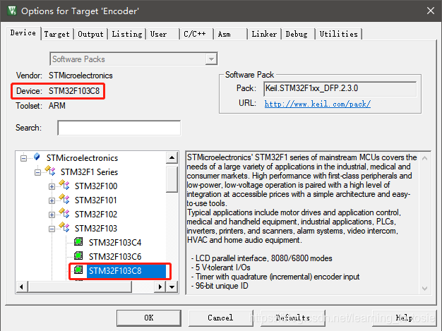
编写好要烧写的程序后,点击菜单栏的【Flash】,选择【Config Flash Tools】。首先,在【Device】页面中选择设备类型,这里是STM32F103C8。
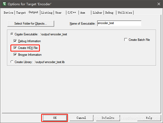
然后,切换到【Output】页面,勾选【Create HEX File】,最后点击【OK】。
回到Keil主界面,点击【Build】编译项目,部分输出如下:
Build started: Project: encoder_test
*** Using Compiler 'V5.06 update 6 (build 750)', folder: 'D:\Keil_v5\ARM\ARMCC\Bin'
Build target 'Encoder'
compiling stm32f10x_bkp.c...
..\Sys\stm32f10x.h(53): warning:  #47-D: incompatible redefinition of macro "STM32F10X_MD"
  #define STM32F10X_MD           /* 处理器型号 stm32f103rb */
..\Lib\src\stm32f10x_bkp.c: 1 warning, 0 errors
...
linking...
Program Size: Code=9612 RO-data=336 RW-data=68 ZI-data=1636
FromELF: creating hex file...
".\output\encoder_test.axf" - 0 Error(s), 30 Warning(s).
Build Time Elapsed:  00:00:07
可以看到,没有报错,而且生成了hex文件,这正是我们需要的。
3、准备STM32最小系统开发板
3.1、设置BOOT方式
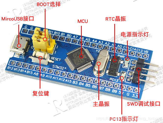
STM32最小系统开发板如下图所示,这里只看【BOOT选择部分】,上面是BOOT 0,下面是BOOT 1,左侧是0,右侧是1。
有两种BOOT模式,一种为运行模式,另一种为烧写模式,设置方式为:
- 运行模式:BOOT 0为0,BOOT 1为0
- 烧写模式:BOOT 0为1,BOOT 1为0
因为这里要烧写程序,所以将BOOT 0设置为0,BOOT 1设置为0。
3.2、连接USB转TTL CH340G
USB转TTL CH340G示意图:
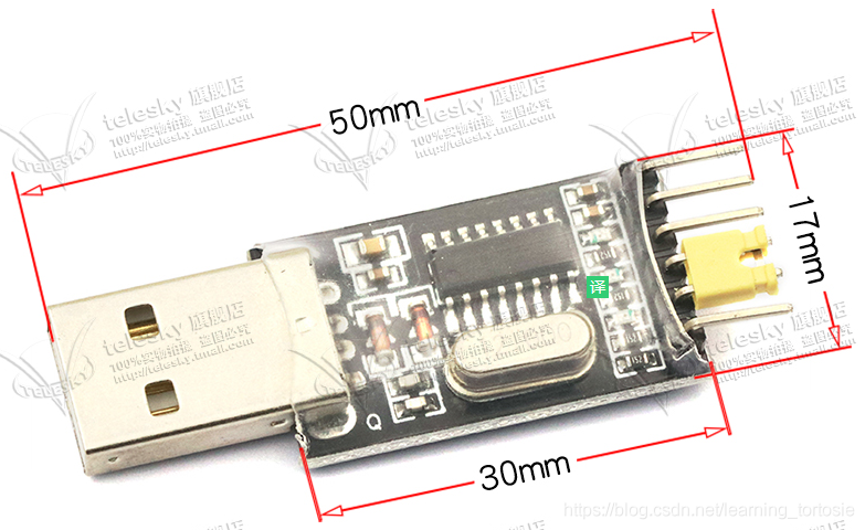
根据下图的接线方式,将USB转TTL CH340G与STM32最小系统开发板连接起来。
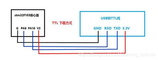
连接好后,将USB转TTL CH340G插入到PC的USB接口中。
4、使用FlyMCU往STM32中烧写程序
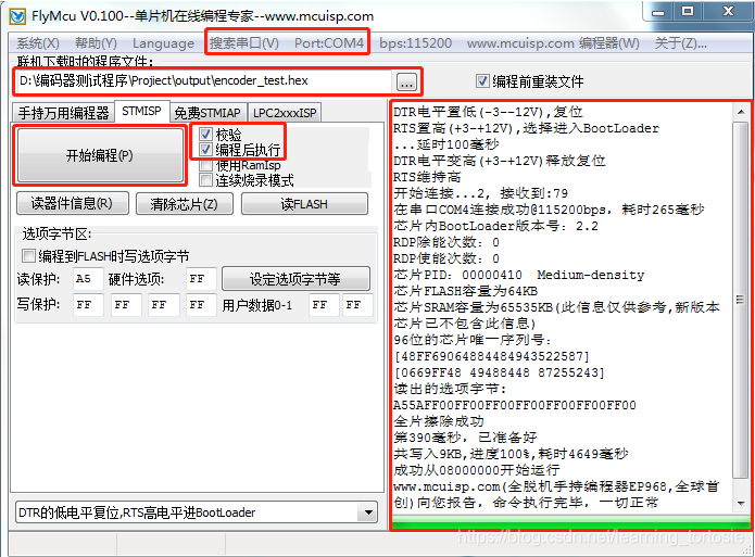
4.1、搜索串口
正常情况下,软件会自动搜索到串口。
4.2、加载hex文件
加载之前生成的hex文件。
4.3、其他设置
勾选【校验】和【编程后执行】。
4.4、烧写
点击【开始编程】,烧写程序。
右侧窗口为输出信息,可以看出,烧写完成。
————————————————
版权声明:本文为CSDN博主「W_Tortoise」的原创文章,遵循CC 4.0 BY-SA版权协议,转载请附上原文出处链接及本声明。
原文链接:https://blog.csdn.net/learning_tortosie/article/details/105156743