在前面的章节中我们介绍了MM32 USB各种功能类型,也介绍了如何通过串口或者J-Link RTT方式实现shell辅助调试方式,但是其都需要依赖额外的工具,比如串口方式就需要USB转TTL,J-Link RTT需要使用J-Link下载器,所以希望有新的方法实现shell,本次我们介绍USB CDC的方式来实现shell功能。
本次我们采用MM32L373 MiniBoard作为测试开发板,验证USB CDC的方式来实现shell功能。
前面已经为大家讲解了shell的串口方法,其实原理一样,只是用MM32 USB枚举成串口设备替代USB转TTL,直接从USB获取数据到MCU,也不需要额外占用MCU的串口,节省资源和硬件,相关的代码都可以从之前的文章获取,本次只是融合两者,改变实现接口,具体代码参考如下:
对于CDC部分,其函数初始化配置及相关全局变量定义内容,代码如下:
#define USBD_POWER                    0

#define USBD_MAX_PACKET0             64

#define USBD_DEVDESC_IDVENDOR      0x2F81 //0x0D28

#define USBD_DEVDESC_IDPRODUCT     0x0001 //0x0204
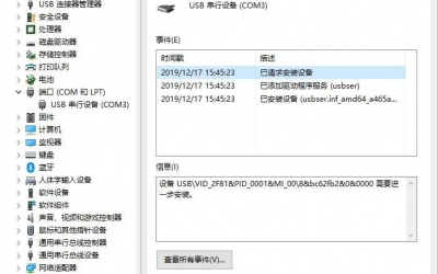
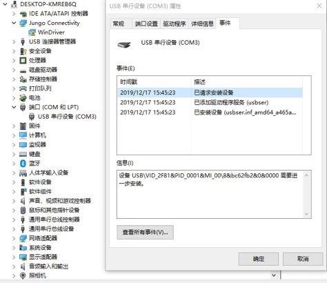
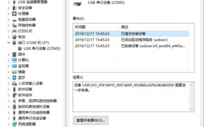
以上是定义的MM32 MCU CDC设备VID和PID,灵动微电子已经获得USB组织授权的VID和PID。当设备插入电脑上,可以查看到如上标识的CDC设备,如图1所示:

对于MM32 MCU的CDC功能来说,
在使用CDC功能之前先调用USB初始化函数来初始化USB协议栈。
int main(void)

{

// USB Device Initialization and connect

usbd_init();

usbd_connect(__TRUE);

while (!usbd_configured())     // Wait for USB Device to configure

{

}

while (1)

{

}

}
对于shell部分其函数初始化配置及相关全局变量定义内容,代码如下:
typedef struct

{

char *command; // shell命令提示符

char buffer[SHELL_COMMAND_MAX_LENGTH]; // shell命令缓冲buffer

unsigned short length; // shell命令长度大小

unsigned short cursor; // shell光标位置偏移

char *param[SHELL_PARAMETER_MAX_NUMBER]; // shell参数变量

char history[SHELL_HISTORY_MAX_NUMBER][SHELL_COMMAND_MAX_LENGTH]; // 历史记录区域

unsigned short historyCount; // 历史记录数量

short historyFlag; // 当前记录偏移位置

short historyOffset; // 历史记录偏移大小

SHELL_CommandTypeDef *commandBase; // 命令表基地址

unsigned short commandNumber; // 命令数量

int keyFuncBase; // 按键响应表基地址

unsigned short keyFuncNumber; // 按键响应数量

SHELL_InputMode status; // shell输入状态

unsigned char isActive; //是不是当前激活的shell

shellRead read; // shell读函数接口

shellWrite write; // shell写函数接口

}SHELL_TypeDef;
如上所示,为对象的定义接口,移植的步骤先定义一个shell对象,即:SHELL_TypeDef cdc_shell,然后实例化对象的操作接口,具体说明看注释,对于其中我们需要关注的是shell的读写接口。由于本次我们使用USB CDC接收和发送数据,所以我们只需要在USB CDC的函数中处理接收到的数据即可,我们使用shellHandler(&cdc_shell, EP2RXBuff[i]);来处理数据的交互,具体函数代码参考串口shell代码。
shell的发送接口,只需要把数据拷贝到buffer即可。
shell的读写接口移植到CDC上,代码如下:
void  USBD_CDC_TASK(void)
{
uint8_t i, count;

NotifyOnStatusChange();
if (CDC_UART ->ISR & 0x08)
{
CDC_UART ->GCR &= ~(3 << 3);
CDC_UART ->GCR = 3 << 3;
UART_ClearITPendingBit(CDC_UART, UART_OVER_ERR);
}
// USB -> UART
if (EP2ReceiveFlag == 1)
{
EP2ReceiveFlag = 0;
for (i = 0; i < RxBufLen; i++)
shellHandler(&cdc_shell, EP2RXBuff[i]);
}

// UART -> USB
if (EP2TransferFlag == 1)
{
if (TxBufLen > 0)
{
while (USB->rEP2_CTRL & 0x80);
if (TxBufLen > 64)
{
UART_ReadData(EP2TXBuff, 64);
count = 64;
TxBufLen -= 64;
}
else
{
UART_ReadData(EP2TXBuff, TxBufLen);
count = TxBufLen;
TxBufLen = 0;
}
usb_buf_busy_flag = 1;
for (i = 0; i < count; i++)
{
USB->rEP2_FIFO = *(EP2TXBuff + i);
}
if ((USB ->rEP2_AVIL & 0x3f) == count)
{
USB->rEP2_CTRL = 0x80 | count;
}
else
{
USB->rTOP |= 1 << 3;
USB->rTOP &= ~(1 << 3);
}
USB->rEP2_CTRL = 0x80 | count;
if (0 == TxBufLen)
EP2TransferFlag = 0;
}
}
}
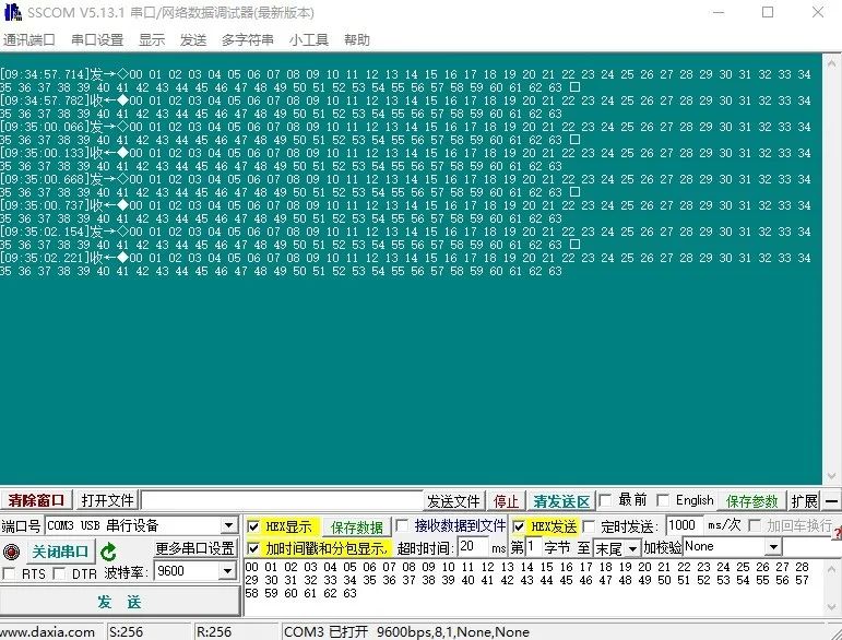
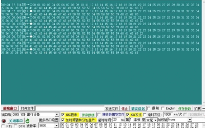
如上,我们就完成通过MM32 MCU的CDC实现shell调试功能,用串口助手打开虚拟串口,用CDC shell测试发送数据,结果如下:

以上就是MM32 MCU USB的CDC shell功能。
本文转自:灵动MM32MCU